本文始於2009年筆者初入SI、PI領域時,使用Ansoft HFSS v10.0完成操作,模擬步驟與說明較為簡略,也沒有附上範例檔。2012年重新以HFSS v14.0撰寫本文,並附上範例檔供學習參考。此例的重點在了解Driven Terminal下wave port + de-embed使用,與differential pair的odd mode、even mode field,並做特性阻抗最佳化求解。
Get Started
Create 3D Model
Create Wave Port Excitation
Analysis Setup
Create Reports
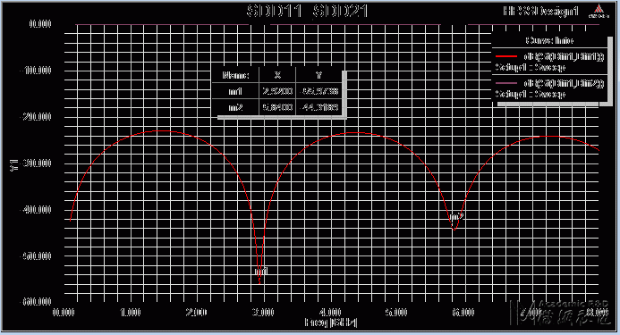
-- SDD11 plot
-- Export S-parameter
Create Field Overlay
Design Optimize
Animate Field Overlay
Export Differential S-parameter
Transfer Diff. S-parameter to Single-end S-parameter
問題與討論
11.1 De-embed有什麼優點?
11.2 在HFSS中,如何觀察Zin(從port往系統網路看)、埠端阻抗(port Zo)與傳輸線特性阻抗(Zo)?
11.3 為何此例在HFSS內模擬時,不需要設background (air box)? 又此例stripline的reference plane在哪裡?
11.4 什麼時候用wave port,甚麼時候用lump port?此例如果改成lump port,結果會不會相同?
11.5 如果step3.3不用de-embed,而是真正建一段線長1000mils的傳輸線取代本例100mils線長+900mils de-embed,結果相同嗎?
參考資料
Get Started 
1.1 Setting Tool Options
Tools Options HFSS Options: 被複製的幾何形物件,默認有一樣的邊界特性
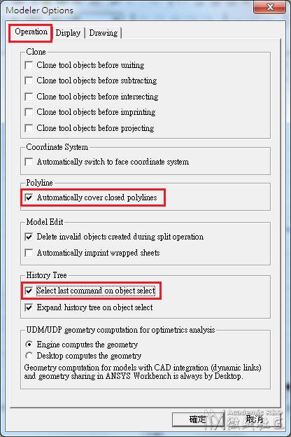
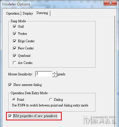
Tools Options Modeler Options:
1.2 Open a new project:File New
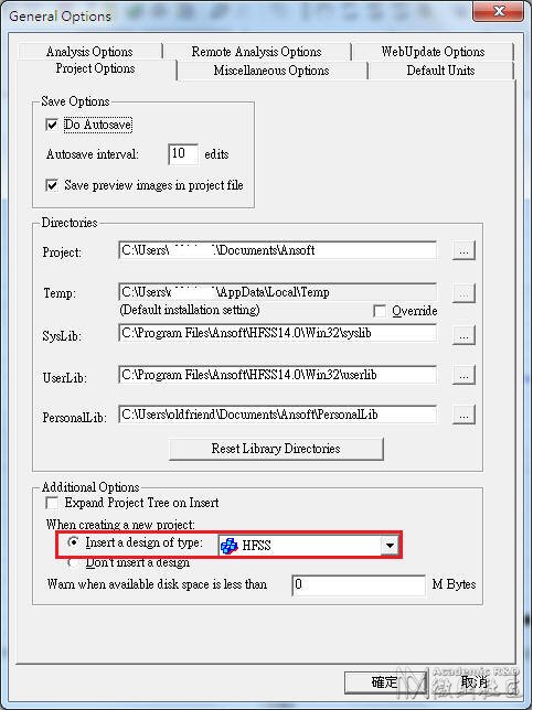
如果希望一開啟HFSS就已經有一個new project,請從Tools Options General Options:
1.3 Set Solution Type:HFSS Solution Type, choose [Driven Terminal] for this example
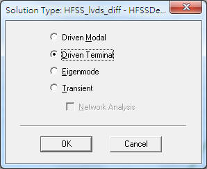
 讀者可以用Help搜尋[Solution Type]的說明:
[Driven Mode] is for calculating the mode-based S-parameters of passive, high-frequency structures such as microstrips, waveguides, and transmission lines which are "driven" by a source, and for computing incident plane wave scattering. The S-matrix solution will be expressed in terms of the incident and reflected powers of waveguide modes.
[Driven Terminal] is for calculating theterminal-based S-parameters of passive, high-frequency structures with multi-conductor transmission line ports. This solution type results in a terminal-based description in terms of voltages and currents.
[Eigen Mode] is for calculating the Eigenmodes, or resonances, of a structure. The Eigenmode solver finds the resonant frequencies of the structure and the fields at those resonant frequencies. Eigenmode designs cannot contain design parameters that depend on frequency.
[Transient] is for calculating problems in the time domain. It employs a time-domain "transient" solver. Typically applications include (The mode appears from HFSS 13)
1.4 Set Model Units:Modeler Units, select "mil"
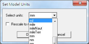
 小心不要選錯成[mile],差一字可是差很多的
1.5 Set Default Material:直接從工具列選擇 
在"Search by Name"欄位內填入"pec" (means perfect conductor),下面視窗內即會自動搜尋到該名稱的材質,然後按"確定"即可。這個設定步驟,是確保我們等等畫的signal trace材質是良導體(默認pec)。
 雖然本例使用的材質介電係數是不隨頻率變化,但HFSS可設定隨頻率變化的介電係數,請參閱
Create 3D Model 
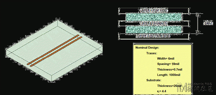
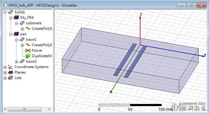
目標是模擬線寬W=6mils、線距S=18mils、線長1000mils的differential pair,堆疊結構則是線銅厚0.7mils,訊號線夾在高度26mils的substrate中,介電係數4.4,沒有另外再畫其他的金屬平面 。
2.1 Create trace 1, trace 2
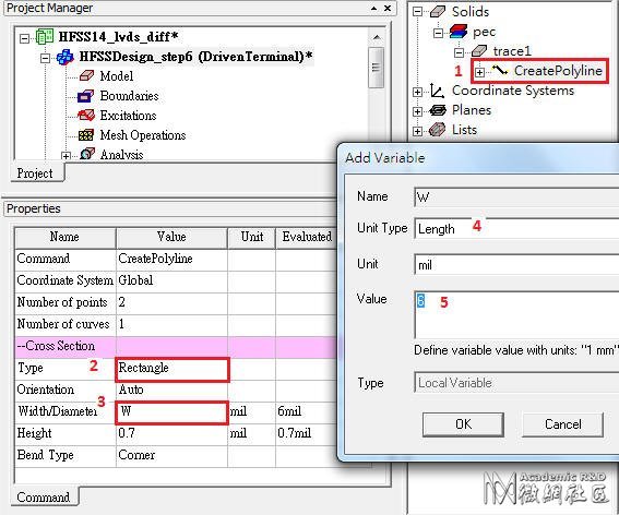
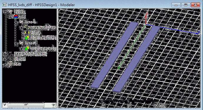
2.1.1 畫傳輸線實體結構有兩種方法,HFSS v12以前的文件是用Drow Box,HFSS v13以後的文件是用DrawLine + CreatePolyline。後者在畫傳輸線的應用上,會方便許多。
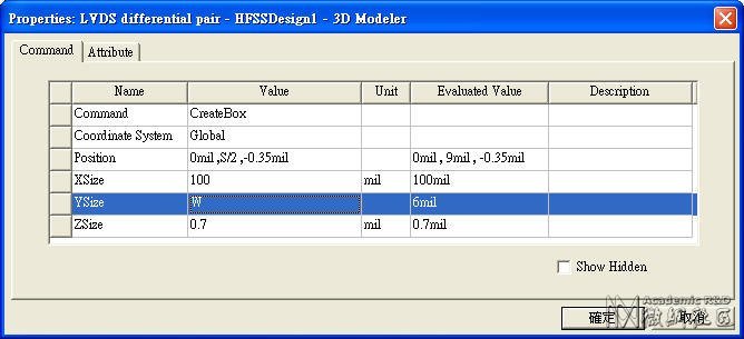
Draw Box 按下後,下方狀態列會出現座標輸入欄位 ,請輸入對角兩點的座標(基準座標與相對座標)
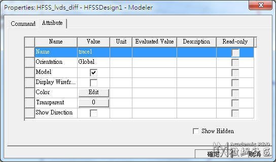
接著會彈出物件屬性編輯窗,將原本"position"該列中的9mil改寫成S/2,接著在跳出的變數定義窗中定義S=18mil;同理定義W=6mil。然後選擇"Attribute"標籤頁,更改Name type=trace1
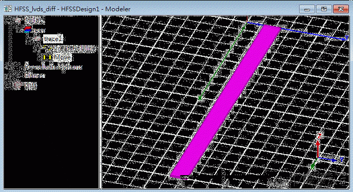
Draw Line from (0, 0, 0) to (100, 0, 0), and rename in [Attribute] tab as "trace1"
Edit Select All
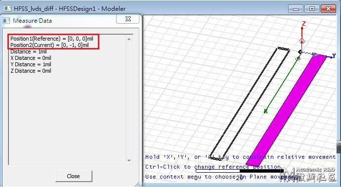
Edit Arrange Move from (0, 0, 0) to (0, 9, 0), and a Properties window will launch
2.1.2 上述步驟完成後,可以從View Fit All Active View或按Ctrl+D 檢視全貌 
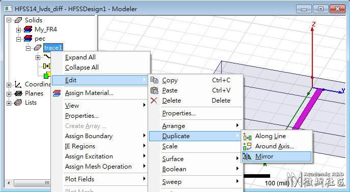
2.1.3 先在History Tree內由Object pec trace1選定上一步驟所繪製的trace1,按滑鼠右鍵選擇"Mirror"
以上步驟,也可以由Edit Select All Visible + Edit Duplicate Mirror完成。
此時游標變成一個較大的黑色實心菱形,以指定鏡射方向;當然也可以透過輸入基準座標與相對座標來指定鏡射方向。(往-Y軸方向翻)
接著會彈出物件屬性編輯窗,選擇"Attribute"標籤頁,更改Name type=trace2
2.2 Create Substrate of permittivity =4.4
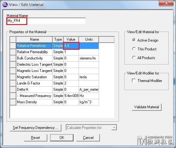
直接從工具列選擇  ,按"Add Material",新建一個電介係數為4.4的材質,命名為My_FR4
畫包圍傳輸線的substrate (dielectric)實體結構同樣有兩種方法
Draw Box按下後,請輸入基準座標與相對座標(0,-100,-13)(100,200,26),然後在屬性設定窗中,在"Attribute"標籤頁內,將名稱改成substrate,透明度Transparency改成0.8
Draw Line from (0, 0, 0) to (100, 0, 0),然後其Properties內的Type選[Rectangle],Width/Diameter=200,High=26,透明度設0.8
Create Wave Port Excitation 
3.1 Create wave port excitation p1, p2
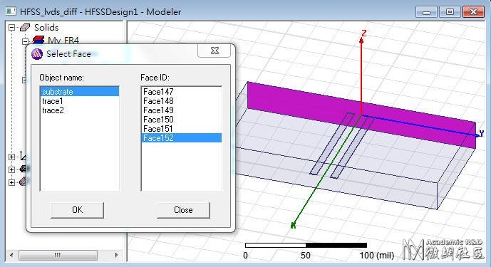
3.1.1 Edit Select Faces
Edit Select By Name
3.1.2 HFSS Excitations Assign Wave Port
將此wave port命名為p1, 然後按OK。
 導體延伸到air box,wave port直接下在air box的面上,這是典型的external wave port;另有一種internal wave port的做法,需要在wave port的另一邊貼一個導體平面。
同理在對面的face也建wave port。
3.2 Set Differential Pairs
HFSS Excitations Differential Pairs 或到Project window內的Excitation點右鍵選擇[Differential Pairs]
連續按兩次[New Pair]
3.3 Set de-embed distance of the transmission line
HFSS List 選擇[Excitation] tab,也可以看到p1, p2
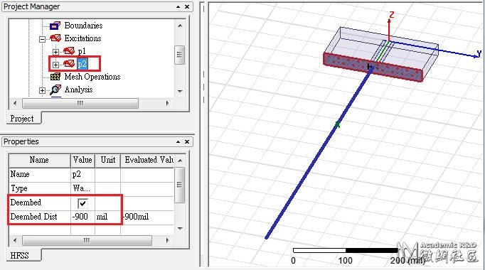
選擇p2,然後按"Properties",[Deembed]打勾,[Deembed Distance]填-900mil
 [Deembed]這是HFSS在模擬傳輸線時,一個很好用的功能;user只需建一小段的固定傳輸線模型,然後設定De-embed Distance,即可任意調整傳輸線長度,不需rerun而得到模擬結果。以此例來說,我們想要模擬1000mils長的傳輸線,但我們所建的模型只有100mils,所以設定De-embed Distance=-900mils(即延長傳輸線長度900mils)。設定後可以看到一根粗的藍色線,標示傳輸線長度的延伸。
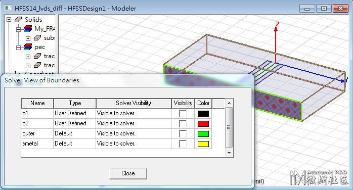
3.4 Verify the boundary:HFSS Boundary Display (Solver View)
背景環境有默認的boundary
 本例不需要另外框一個背景輻射空間,原因是因為訊號線已經被包在一個已經有設定屬性的材質裡了(substrate, My_FR4),且因為wave port正好佈滿兩側,wave port的四邊所延伸的四面,其邊界條件默認是Perfect Conductor。
或是按滑鼠右鍵 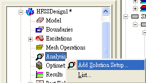
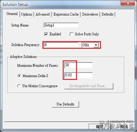
[Solution Frequency]若取整個系統設計的最大考慮頻寬,mesh會切最多,模擬時間較長,但模擬也會最準。
 對於天線設計,因為我們通常只在意天線操作頻帶,所以這個值可以設天線阻抗最低的操作頻點;但對於SI設計的應用,則建議取0.5/Tr值。
[Maximum Number of Passes] is the maximum number of mesh refinement cycles for HFSS to perform. 設大於2(含)就會mesh refinement,設的越大,可容許的refine tuning次數越多,模擬時消耗的記憶體也越多(一般設10~20), 但若mesh refinement提前達到[Maximum Delta S]條件就會停下來
[Minimum Converged Passes]設定建議從1改成2,mesh refinement的次數會多一次,但可以確保meshing切的真正足夠
Zero order、First order(default)、Second order,會分別自動對應"Lambda Refinement"為Target 0.1、0.3333、0.6667,越高階order越適合用來解結構複雜的模型,但時間也會花較多。HFSS v12以後多了[Mixed Order],建議默認用此 檔設定,會在結構較複雜或電場變化較大的地方,自動以high order處理
[Enable Iterative Solver]:The iterative solver significantly reduces memory usage, and it can also provide a savings in the solution time for large simulations.
4.2 HFSS Analysis Setup Add Frequency Sweep
或是按滑鼠右鍵 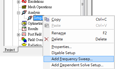
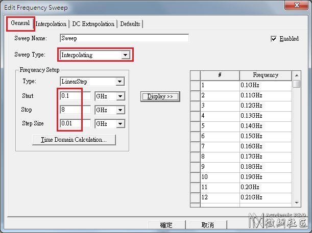
 [DC Extrapolation]只有當[Sweep Type]選擇[Interpolating]才 有,且Start Frequency設0時,[DC Extrapolation]的最小頻率才能指定
 [Sweep Type] 選[Discrete]就是針對指定的頻點老實求解,費時較久但較準確, 一般5GHz內的頻寬適用。[Fast]適用於 局部窄頻段內頻率響應變化大的題目,如特性振盪的頻段(resonant frequency),可以在指定求解的頻點小範圍內精準。[Interpolating]則適用於寬頻帶(10GHz~)且頻率響應較緩和的(smooth)題目。
4.3 HFSS Validation Check 
HFSS Analyze All 
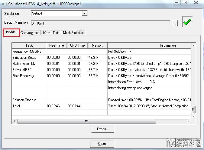
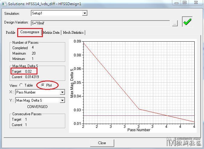
查看模擬過程中做了幾次疊代才得到收斂值
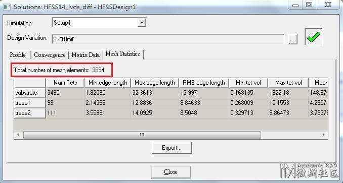
總共切多少mesh
每次跑的結果不一定相同,若電腦太遜,還有可能跑一跑就Error而跑不出結果。這些訊息可以在執行過程中real time check。
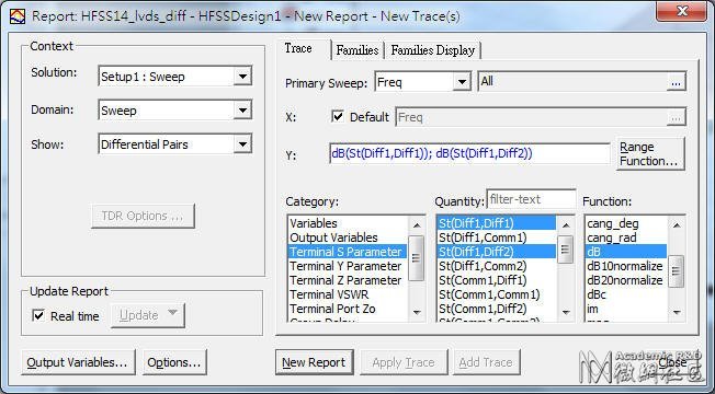
5.2 S-parameter plot 
HFSS Results Create Terminal Solution Data Report Rectangular Plot
5.3 從SDD11可以看出此1000mils的傳輸線,在2.92GHz、5.84GHz有共振點
5.4 Export S-parameter 
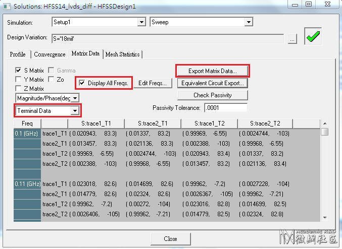
HFSS Results Solution Data,[Display All Freqs]打勾,按[Export Matrix Data]即可另存.snp file (.snp)
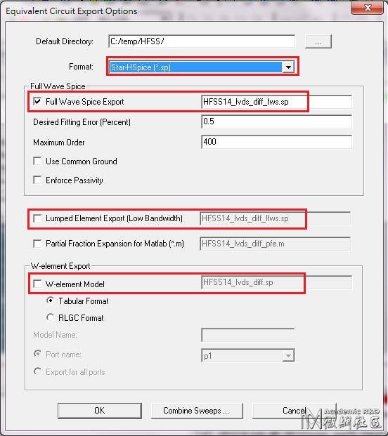
若按[Equivalent Circuit Export],則可輸出PSpice.lib或HSPICE.sp
Create Field Overlay 
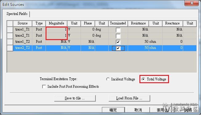
6.1 Set the field excitation:HFSS Fields Edit Sources,設定p1 drive,p2 terminated
或是按滑鼠右鍵 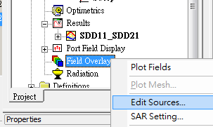
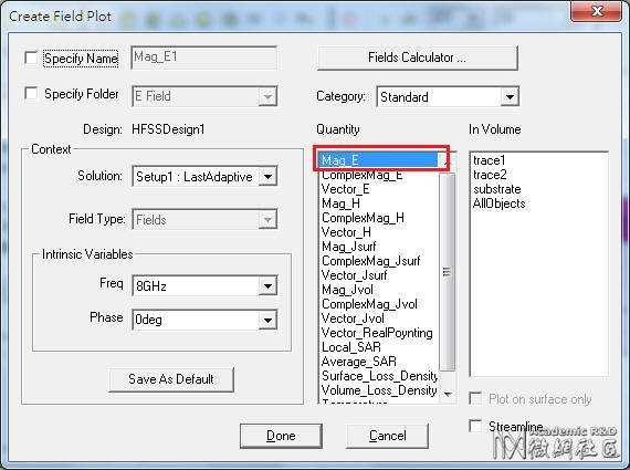
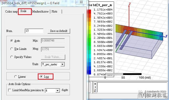
6.2 Create a field plot:HFSS Fields Fields E Mag_E (能量大小顯示)
HFSS Fields Modify Plot Attributes
或是 
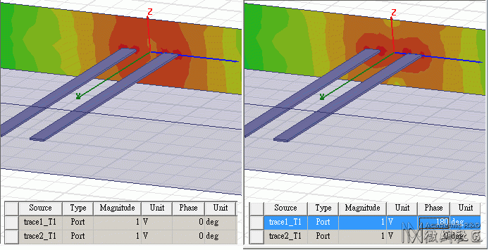
若從[Edit Source]修改[Phase]設定,可以看出Mag_E場圖的變化 ,下圖左是common mode,圖右是differential mode
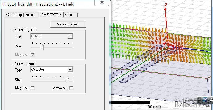
6.3 Create a field plot:HFSS Fields Plot Fields E Vector_E (方向顯示)
HFSS Fields Modify Plot Attributes
Design Optimize 
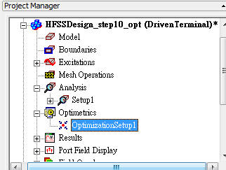
在6.5<w<7.5mils,16.5<sAnimate Field Overlay 
8.1 Double click on Mag_E
8.2 Mag_E Animate
8.3 Setup Animation:可以分別選擇"Swept Variable"為Phase、S、W,按OK
Export Differential S-parameter 
Follow step5.4
Transfer Diff. S-parameter to Single-end S-parameter 
HFSS可以支持吐出single-end S-parameter as step5.4,或是differential S-parameter as step9。但如果我們並沒有3D model,只有S-parameter (.snp),那如何在single-end與differential間做轉換呢?
Designer 6.0有提供一個非常好用的功能:Tool Net Data Explorer,不但可以把single-end轉differential S-parameter,還可以把S參數轉Z參數
Edit Define Differential Pairs
問題與討論 
11.1 De-embed有什麼優點?
Ans:讀者可以把本文step3.3中的[Deembed Distance]值,改填-900mm(不需rerun),即可看到S plot結果如下,諧振頻點從低頻到高頻(變多 變密),S11也從-15dB下降到-24dB。透過這方式,user不需重新建模,可以快速調整結構長度,而且不需重新mesh或模擬計算。如果不用這方式,而是把3D model的長度參數設變數,那越長的結構模擬時間會增加越多。
11.2 在HFSS中,如何觀察Zin(從port往系統網路看)、埠端阻抗(port Zo)與傳輸線特性阻抗(Zo)?
Ans:在step5.2中,Category:Terminal Port Zo即是指port端阻抗,而不是傳輸線上的特性阻抗,不要搞錯了。Category:Terminal Z Parameter即是指從port往系統網路看的阻抗Z11 。而傳輸線的特性阻抗若要在HFSS查看,則要到時域裡看TDR。
11.3 為何此例在HFSS模擬時,不需要設background (air box)? 又此例stripline的reference plane在哪裡?
Ans:默認的background boundary (substrate表面)是理想導體,若不考慮reference plane的導電率,傳輸線就直接以boundary face當reference plane。為了驗證這點,我們在上下表面各貼一層Perfect E的sheet當reference plane,重新下wave port,且該wave port同時以此上下兩sheet為reference,模擬結果如下,與step5.3一模一樣
11.4 什麼時候用wave port,甚麼時候用lump port?此例如果改成lump port,結果會不會相同?
Ans:wave port是以平面能量來計算,lump port是以V/I來計算,如果lump port夠短,可以得到很接近的S-parameter模擬結果 ,除非wave port size設的不對。 一般天線或波導管設計建議用wave port,SI設計建議用lump port,但沒有絕對。只有wave port可以用de-embed,並且可以一個port對上下plane同時reference。更正:lump port也可設de-embed,即K掉lump port的電感效應port calibration(所以我們建議lump port越小越好),也可以設成參考上下兩平面。
11.5 如果step3.3不用de-embed,而是真正建一段線長1000mils的傳輸線取代本例100mils線長+900mils de-embed,結果相同嗎?
Ans:與step5.3的模擬結果相比, 在3GHz S11大約差4dB,諧振頻點約偏移3%,在6GHz S11大約差12dB。故太長的wave port de-embed是會造成S11誤差的 ,雖然這誤差很小,建議de-embed長度最好不要超過l/10
參考資料 
12.1 SI issue for high speed serial differential interconnection -- 中華大學 薛光華老師
12.2 EMC Considerations for Differential Lines , 2007
12.3 Differential Signals are NOT Immune to EMI/EMC Concerns! , 2010
12.4 HFSS v13,v12與v11的差異? -- ANSYS
</w<7.5mils,16.5<s
00d44 发表于 2012-12-12 22:27
你也可以定期转载一些过来,大家共同学习下
支持版主工作,没有问题哈。我抽时间转些大家一起学习~~
在求解设置中,[Enable Iterative Solver]:The iterative solver significantly reduces memory usage, and it can also provide a savings in the solution time for large simulations. 这个普遍适用于大型问题么? 我仿真个天线阵列,总是提示内存不够。。用这个好使么?



讀者可以用Help搜尋[Solution Type]的說明:
[Driven Mode] is for calculating the mode-based S-parameters of passive, high-frequency structures such as microstrips, waveguides, and transmission lines which are "driven" by a source, and for computing incident plane wave scattering. The S-matrix solution will be expressed in terms of the incident and reflected powers of waveguide modes.[Driven Terminal] is for calculating theterminal-based S-parameters of passive, high-frequency structures with multi-conductor transmission line ports. This solution type results in a terminal-based description in terms of voltages and currents.[Eigen Mode] is for calculating the Eigenmodes, or resonances, of a structure. The Eigenmode solver finds the resonant frequencies of the structure and the fields at those resonant frequencies. Eigenmode designs cannot contain design parameters that depend on frequency.[Transient] is for calculating problems in the time domain. It employs a time-domain "transient" solver. Typically applications include (The mode appears from HFSS 13)1.4 Set Model Units:Modeler Units, select "mil"
小心不要選錯成[mile],差一字可是差很多的
1.5 Set Default Material:直接從工具列選擇在"Search by Name"欄位內填入"pec" (means perfect conductor),下面視窗內即會自動搜尋到該名稱的材質,然後按"確定"即可。這個設定步驟,是確保我們等等畫的signal trace材質是良導體(默認pec)。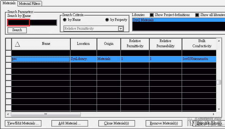
雖然本例使用的材質介電係數是不隨頻率變化,但HFSS可設定隨頻率變化的介電係數,請參閱

按下後,下方狀態列會出現座標輸入欄位 ,請輸入對角兩點的座標(基準座標與相對座標)

from (0, 0, 0) to (100, 0, 0), and rename in [Attribute] tab as "trace1"
,按"Add Material",新建一個電介係數為4.4的材質,命名為My_FR4

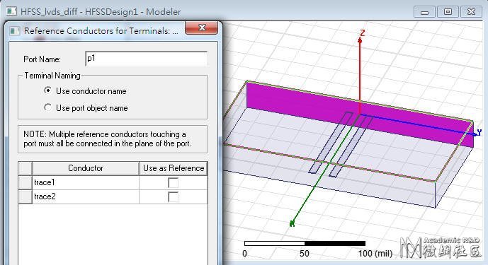
導體延伸到air box,wave port直接下在air box的面上,這是典型的external wave port;另有一種internal wave port的做法,需要在wave port的另一邊貼一個導體平面。
同理在對面的face也建wave port。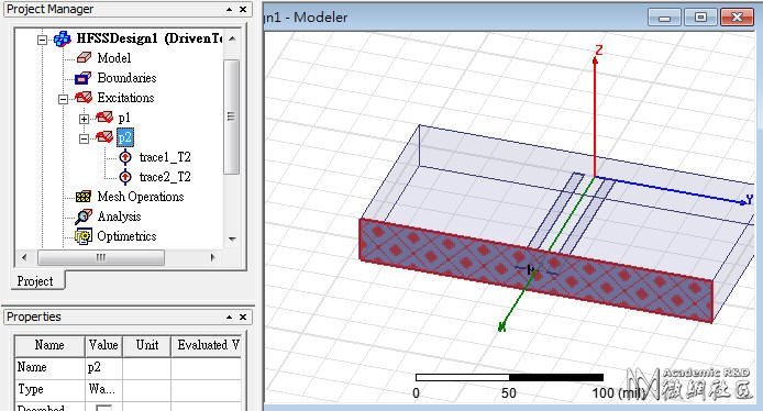
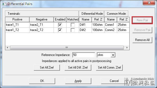
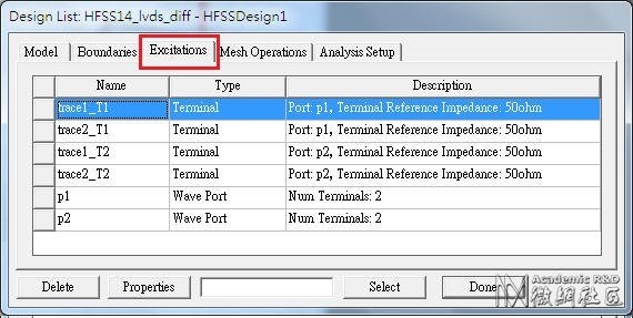
[Deembed]這是HFSS在模擬傳輸線時,一個很好用的功能;user只需建一小段的固定傳輸線模型,然後設定De-embed Distance,即可任意調整傳輸線長度,不需rerun而得到模擬結果。以此例來說,我們想要模擬1000mils長的傳輸線,但我們所建的模型只有100mils,所以設定De-embed Distance=-900mils(即延長傳輸線長度900mils)。設定後可以看到一根粗的藍色線,標示傳輸線長度的延伸。
本例不需要另外框一個背景輻射空間,原因是因為訊號線已經被包在一個已經有設定屬性的材質裡了(substrate, My_FR4),且因為wave port正好佈滿兩側,wave port的四邊所延伸的四面,其邊界條件默認是Perfect Conductor。

對於天線設計,因為我們通常只在意天線操作頻帶,所以這個值可以設天線阻抗最低的操作頻點;但對於SI設計的應用,則建議取0.5/Tr值。
[Maximum Number of Passes] is the maximum number of mesh refinement cycles for HFSS to perform. 設大於2(含)就會mesh refinement,設的越大,可容許的refine tuning次數越多,模擬時消耗的記憶體也越多(一般設10~20), 但若mesh refinement提前達到[Maximum Delta S]條件就會停下來

[DC Extrapolation]只有當[Sweep Type]選擇[Interpolating]才 有,且Start Frequency設0時,[DC Extrapolation]的最小頻率才能指定
[Sweep Type] 選[Discrete]就是針對指定的頻點老實求解,費時較久但較準確, 一般5GHz內的頻寬適用。[Fast]適用於 局部窄頻段內頻率響應變化大的題目,如特性振盪的頻段(resonant frequency),可以在指定求解的頻點小範圍內精準。[Interpolating]則適用於寬頻帶(10GHz~)且頻率響應較緩和的(smooth)題目。







 WS03_1_hfss_si_sldiff.zip (134.27 KB)