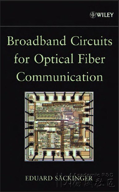
Broadband Circuits for Optical Fiber Communication:
Preface
I Introduction
Contents
2 Optical Fiber
2.1 Loss and Bandwidth
2.2 Dispersion
2.3 Nonlinearities
2.4
2.5 Summary
2.6 Problems
Pulse Spreading due to Chromatic Dispersion
3 Photodetectors
3.1 p-i-n Photodetector
3.2 Avalanche Photodetector
3.3
3.4 Summary
3.5 Problems
p-i-n Detector with Optical Preamplifier
vii
i
i1
i1
14
18
19
22
23
25
25
31
34
40
42
xi
TEAM LinG
xii CONTENTS
4 Receiver Fundamentals
4.1 Receiver Model
4.2 Bit-Error Rate
4.3 Sensitivity
4.4 Personick Integrals
4.5 Power Penalty
4.6 Bandwidth
4.7 Adaptive Equalizer
4.8 Nonlinearity
4.9 Jitter
4.10 Decision Threshold Control
4. I I Forward Error Correction
4.12 Summary
4.13 Problems
5 Transimpedance Ampl@ers
5. I TIA Specifications
5. 1. I Transimpedance
5.1.2 Input Overload Current
5.1.3
5.1.4 Input-Referred Noise Current
5.1.5 Bandwidth and Group-Delay Variation
5.2. I Low- and High-Impedance Front-Ends
5.2.2 Shunt Feedback TIA
5.2.3 Noise Optimization
5.2.4 Adaptive Transimpedance
5.2.5 Post Amplijier
5.2.6 Common-BaseIGate Input Stage
5.2.7 Current-Mode TIA
5.2.8 Active-Feedback TIA
5.2.9 Inductive Input Coupling
5.2. 10 Differential TIA and Offset Control
5.2.1 I Burst-Mode TIA
5.2.12 Analog Receiver
5.3 TIA Circuit Implementations
5.3. I
5.3.2
5.3.3 CMOS Technology
Maximum Input Current for Linear Operation
5.2 TIA Circuit Concepts
MESFET and HFET Technology
BJI: BiCMOS, and HBT Technology
45
45
47
54
66
70
73
82
86
90
95
96
100
101
I 05
I 05
I 05
107
I 08
108
I I1
112
112
113
121
130
132
133
134
135
136
137
141
143
145
145
147
149
TEAM LinG
CONTENTS xiii
5.4 ProductExamples
5.5 Research Directions
5.6 Summary
5.7 Problems
6 Main Amplifers
6. I Limiting vs. Automatic Gain Control (AGC)
6.2 MA Specifications
6.2.1 Gain
6.2.2 Bandwidth and Group-Delay Variation
6.2.3 Noise Figure
6.2.4 Input Dynamic Range
6.2.5 Input Ofset Voltage
6.2.6 Low-Frequency Cutof
6.2.7 AM-to-PM Conversion
6.3.1 Multistage Amplifier
6.3.2 Techniques for Broadband Stages
6.3.3 Ofset Compensation
6.3.4 Automatic Gain Control
6.3.5 Loss of Signal Detection
6.3.6 Burst-Mode Amplifier
6.4. I
6.4.2 BJT and HBT Technology
6.4.3 CMOS Technology
6.3 MA Circuit Concepts
6.4 MA Circuit Implementations
MESFET and HFET Technology
6.5 Product Examples
6.6 Research Directions
6.7 Summary
6.8 Problems
7 Optical Transmitters
7. I Transmitter Specijications
7.2 Lasers
7.3 Modulators
7.4
7.5 Summary
7.6 Problems
Limits in Optical Communication Systems
151
151
154
156
159
159
161
161
I 64
I 65
169
171
I 73
175
I 76
I 76
I 79
203
207
211
212
213
21 3
215
221
224
226
22 7
228
233
234
237
247
253
256
257
TEAM LinG
xiv CONTENTS
8 Laser and Modulator Drivers
8. I Driver SpeciJications
8.1.1 Modulation and Bias Current Range
(Laser Drivers)
8.1.2 Output Voltage Range (Laser Drivers)
8.1.3 Modulation and Bias Voltage Range
(Modulator Drivers)
8.1.4 Power Dissipation
8.1.5 Rise and Fall Times
8.1.6 Pulse- Width Distortion
8. I . 7 Jitter Generation
8.1.8 Eye-Diagram Mask Test
8.2 Driver Circuit Concepts
8.2. I Current-Steering Output Stage
8.2.2 Back Termination
8.2.3 Predrive r
8.2.4 Pulse- Width Control
8.2.5 Data Retiming
8.2.6 Automatic Power Control (Lasers)
8.2.7 End-of-Life Detection (Lasers)
8.2.8
8.2.9 Burst-Mode Laser Driver
8.2. I 0 Analog Laser/Modulator Driver
8.3.1 MESFET and HFET Technology
8.3.2 BJT and HBT Technology
8.3.3 CMOS Technology
Automatic Bias Control (MZ Modulators)
8.3 Driver Circuit Implementations
8.4 Product Examples
8.5 Research Directions
8.6 Summary
8.7 Problems
Appendix A Eye Diagrams
Appendix B Differential Circuits
B.1 Differential Mode and Common Mode
B.2 The Modes of Currents and Impedances
B.3 Common-Mode and Power-Supply Rejection
259
259
259
261
261
263
264
265
265
267
268
268
2 73
2 76
2 79
280
282
285
286
287
290
294
294
297
302
305
305
308
309
313
32 I
322
324
325
TEAM LinG
CONTENTS XV
Appendix C S Parameters
C. I Dejinition and Simulation
C.2 Matching Considerations
C.3 Diflerential S Parameters
Appendix D Transistors and Technologies
D.1 MOSFET and MESFET
0.2 Heterostructure FET (HFET)
0.3 Bipolar Junction Transistor (BJT)
0.4 Heterojunction Bipolar Transistor (HBT)
Appendix E Answers to the Problems
Appendix F Notation
Appendix G Symbols
Appendix H Acronyms
32 9
329
333
339
343
343
348
351
355
359
385
387
399
References 407
Index 425
感谢楼主分享
我有88000多了,给我加别的分吧,呵呵
:51bbthanks
下来看看,谢谢。
非常感谢楼主分享
